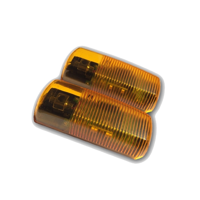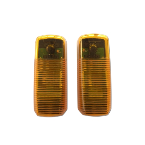

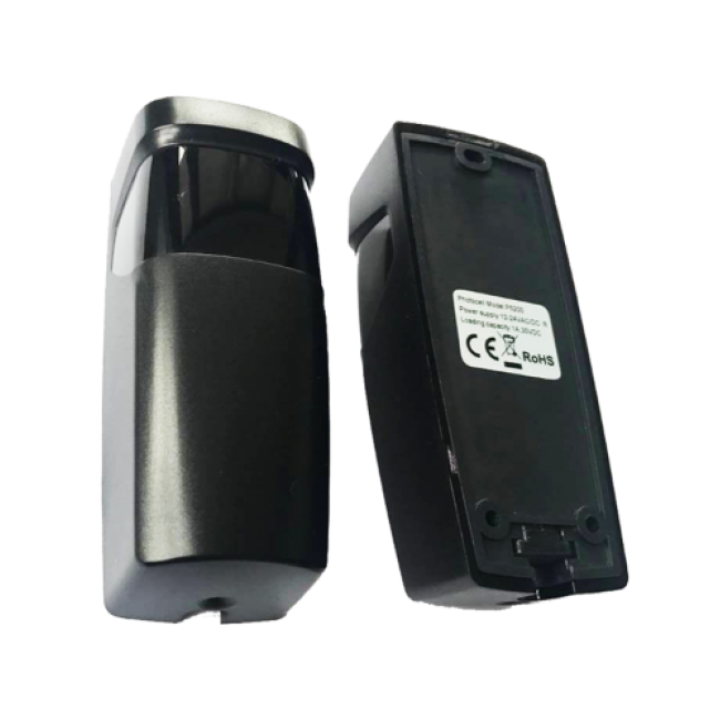
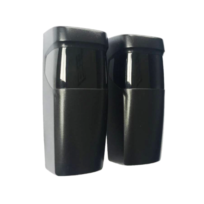

Gate Photocell P5200
Gate photocell access control gate photocell P5200
Packaging & Delivery
-
Product size
11 x 9 x 4 cm
-
Product weight
139 g
-
CTN. Spec
38*37*20 cm / 60Set
-
G.W/N.W
8.5 / 6.9 kg
-
Certification
CE
-
Color
Dark purple
-
Working voltage
12-24 VAC/DC
-
Product size
100*40*35mm
-
Product weight
107g
-
Loading capacity
1A/30VDC
-
Working temperature
-20℃ to 60℃
-
Wavelength
940nm
-
IP Level
IP54
-
Working current
Emitter: ≤8mA; receiver: ≤30mA
-
Angle of opposite emission
≤5°
-
Receiver range
≥15m
-
Internal Rotation System Adjustable Angel
Angle adjustment of PCBA ±90°
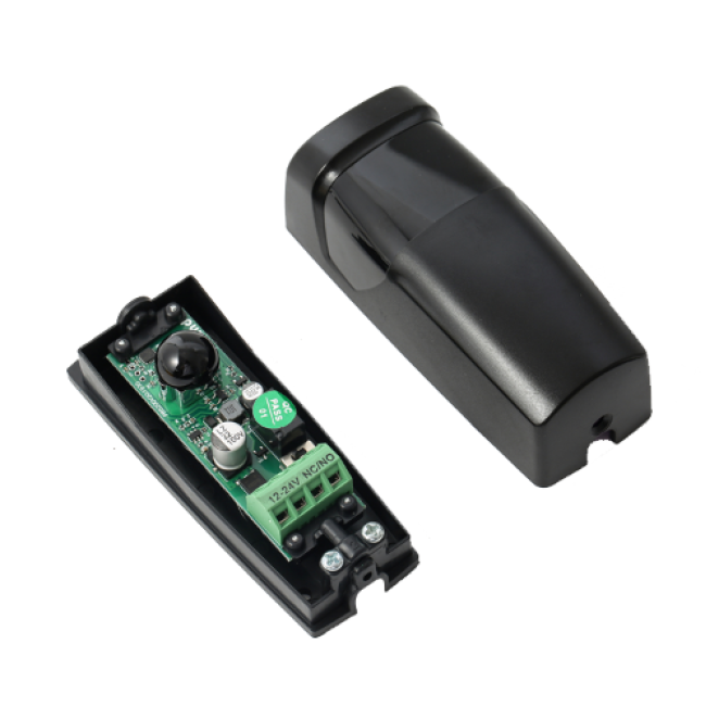
Gate Photocell P5200
I. Technical Specification
1. Working voltage: 12~24VAC/DC
2. Working current(24VDC):emitter: ≤8mA receiver: ≤30mA
3. Photocell wavelength: 940nm
4. Angle of emission: ≤±5°
5. Receiving range: ≥12m
6. Angel adjustment of PCBA: ±90°
7. Working temperature: -20℃~+60℃
8. Relay contact loading capacity: 1A/30VDC
9. Size: 100*40*35mm
10. Waterproof level: IP54
11. Weight: 107g
II. Safety Instruction
1. For security, please read the user manual carefully before initial operation;
2. This photocell is without any fuse, so Please make sure the power is off before installation;
3. This product is only used for the equipment which will not cause life or property hazards when a breakdown happens or its security risks have been already eliminated;
4. Please guarantee the products used in effective working range.
III. Picture Display
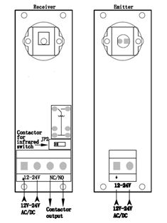
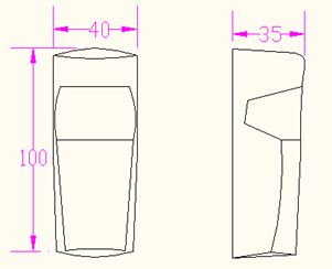
IV. Installation instruction
4.1 Receive module JP2 in above picture (PR5200) is the option switch for NO and NC of photocell switch.
4.1.1 When toggle switch JP2 at NC, it is normally open without power
4.1.2 When toggle switch JP2 at NO, it is normally close without power
4.2. Installation
4.2.1 The photocells should be installed more than 20cm above the ground (to avoid reflection), and the distance between emitter and receiver should be more than 50cm.
4.2.2 End user should install the photocell receiver on the back of the direct sunlight or other strong light source (±5º) to keep photocell work well steadily.
4.2.3 Avoid installing other infrared photocell emitters within the effective distance of receiver
4.2.4 If the end user need to install other photocells in one same straight line , the receivers could be installed in the two ends and the emitters could be back-to-back installed
4.2.5 Stable installation could avoid the signal of emitter and receiver skewing due to lightly vibrate and the malfunction.
4.2.6 When the product is installed in some place with angle , end user could adjust the PCBA to make the installation better .
4.2.7 Connecting power after checking no error of connecting lines, keep the CAP of emitter and receiver align, receiver LED off; When they are not align, receiver LED on.
4.2.8 Connecting power after checking no error of connecting lines, when toggle switch JP2 at NC, keep the CAP of emitter and receiver align, NC/NOconnect; When the CAP of the emitter and receiver are blocked by obstacle, NC/NOdisconnects. When toggle switch JP2 at NO, the state of NC/NO is opposite to the above phenomenon.
Send your message to us
No need register, just fill in contact info below, we will reply you within 24 hours!