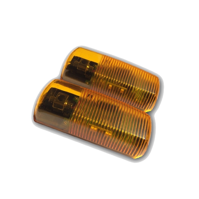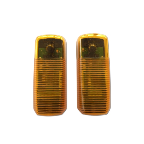
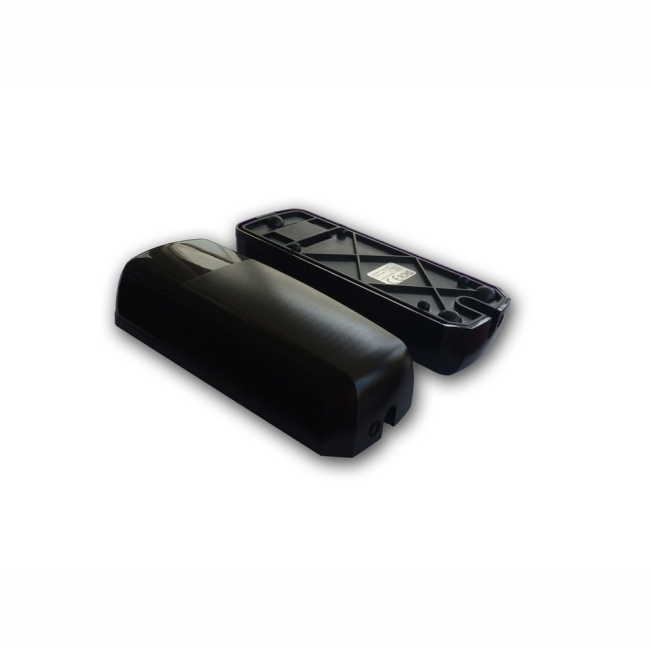


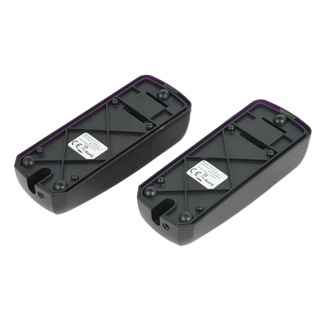
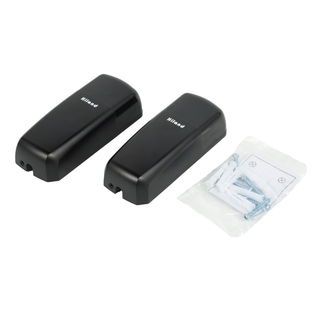

Photocell Sensor for Gate P5103
Automatic gate photocell sensor P5103
Packaging & Delivery
-
Product size
14 x 11.5 x 3.5 cm
-
Product weight
174 g
-
CTN. Spec
38*37*20 cm / 30Set
-
G.W/N.W
6 / 4.5 kg
-
Certification
CE/RoHS
-
Color
Dark purple
-
Working voltage
12-24VAC/DC
-
Product weight
131g
-
Loading capacity
1A/30VDC
-
Working temperature
-20℃ to 60℃
-
Wavelength
940nm
-
IP Level
IP54
-
Working current
24VDC; emitter: ≤15mA receiver: ≤30mA
-
Angle of opposite emission
≤5°
-
Receiver range
≥15m
-
Internal Rotation System Adjustable Angel
No
Photocell Sensor for Gate P5103
I. Technical Specification
1. Working voltage: 12~24VAC/DC
2. Working current: 24VDC; emitter: ≤15mA receiver: ≤30mA
3. Photocell wavelength: 940nm
4. Angle of opposite emission: ≤±5º
5. Receiver range: ≥15m
6. Working temperature: -20º~+60℃
7. Relay contact loading capacity: 1A/30VDC
8. Waterproof grade: IP54
9. Size: 127*50*28mm
II. Safety Instruction
1. For security, please read the user manual carefully before initial operation;
2. Please be sure the power is off before connecting, the product is produced without fuse;
3. It is used only for the manual remote control and wireless control equipment / system, this system must not endanger life or property during the running failure or its security risks have been eliminated;
4. Please operate the product in effective receive range.
III. Installation Instruction
1. The product should be installed more than 20cm upper the ground, and the distance between emitter and receiver shall be more than 0.5 meters;
2. Avoid direct sunlight to emitters and receivers among ±5º, or other direct strong light;
3. Avoid other photocell emitters within effective receive range;
4. If install many photo cells on the same line, can install receivers on two ends and then emitters in the middle back to back which can effectively avoid the third problem.
5. Installation firmly in order to avoid signal bias of emitters and receivers which will easily cause mis-operation.
6. Connecting power after checking no error of connecting lines, emitter LED lights, receiver LED lights,receiver NO/COM connects while NC/COM disconnects; Making the CAP of emitter and receiver align,receiver LED off, NC/COM connects while NO/COM disconnects. If the signal between emitter and receiver is interrupted, receiver LED lights, NC/COM disconnects while NO/COM connects.
Send your message to us
No need register, just fill in contact info below, we will reply you within 24 hours!